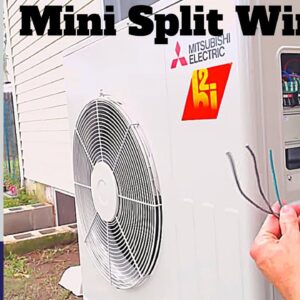
Mitsubishi Mini-Split Heat Pump Wiring: A Comprehensive Guide
Hey everyone, welcome back to our channel! Today, we’re diving into the electrifying world of wiring a Mitsubishi mini-split heat pump unit. This particular model is a single-zone unit, and we’re excited to guide you through the intricacies of the wiring process. Buckle up and let’s get started!
Preparing the Tools and Materials
Before we plunge into the nitty-gritty, let’s gather our essential tools and materials. For this project, you’ll need the following:
- Disconnect switch
- Three THHN wires
- Southwire EZ-IN cable
- MC connector
- Roto split tool
- Utility knife
- Wire strippers
- Fish tape
- Electrical tape
- Anti-short bushings
Understanding the Cable Configuration
Now that we have everything we need, let’s take a closer look at our cable layout. We’ll be utilizing three THHN wires for the high-voltage section, and the Southwire EZ-IN cable will serve as our power wire to the indoor unit and the communication line to ensure seamless connectivity.
It is essential to keep the high-voltage wires safely enclosed, especially since a part of this cable will be exposed to the outside elements. The Southern wire EZ-IN’s casing provides that extra layer of protection we require.
Wiring the Indoor Unit
Entering the Indoor Unit
Stepping inside, we’ve successfully introduced the Southwire EZ-IN cable through the dedicated hole, leading to our indoor head unit. If you are using a standard connector, you would need to remove it by unscrewing the attachment, but here we’re fortunate to have a snap-in MC connector.
Stripping the Cable
Let’s strip the cable back roughly a foot. This means we’ll use our roto split to cut the metal jacket. Positioning the blade at about one foot in, we’ll twist the handle. This action effectively slices through the outer layer. Next, a utility knife will come in handy to remove the remaining sleeve.
Connecting Safely
Ensure you install an anti-short bushing around the wires to shield them from potential damage from the metallic clad. Once that’s done, insert the snap-in connector all the way down, ensuring it fits snugly.
Routing the Wires
Time to slide the wires through! If you encounter any resistance, you might want to fish the wires through using a fish tape to make the process smoother. Once everything is in place, go ahead and snap the connector in securely.
Identifying the Color Codes
Inside the housing, you’ll notice connectors labeled S1, S2, and S3. The black and white wires correspond to the S1 and S2 for power, while the red wire serves as the communication line. Additionally, there’s a ground wire present. Always remember to match the color codes accurately to prevent any mishaps with the outdoor unit.
Handling the Ground Wire
We’re working with 14 gauge wire here, so let’s position it correctly in the wire strippers. It’s paramount to avoid using diagonal cutters, as they might sever some strands. Yielding to their use could bring about unintended consequences.
Affixing the Wires Correctly
Connecting the Ground Wire
The ground wire needs attention first. Given its stranded nature, twist the wire to ensure it’s compact. It’ll go beneath the plate, securely sandwiching in between the washer and the plate. Tightening it is pivotal for a solid connection.
Attaching Power Wires
Next, we’ll focus on the black wire. Loosen the corresponding screw and insert the wire. As we tighten it, it will clasp firmly, providing a reliable connection. Always give it a gentle tug afterward to ensure it has gripped securely.
Finalizing Connections
Once all wires are snugly fit, we need to replace the cover plate carefully. You’ll find the Southwire EZ-IN cable alongside the condensate line and the line set. Next, we’ll need to route these cables through to the outdoor unit.
Preparing the Outdoor Unit
Wire Protection and Routing
As we start routing the wires, let’s not forget to apply anti-short bushings around them to prevent any wear from the metallic conduit. Next, the outdoor connector will facilitate this connection, boasting a rubber lining that ensures a tight seal.
Sealing Connections
With the connectors prepared, it’s instrumental to keep the connection secure yet loose enough for easy adjustments. Passed through correctly, tighten it down to ensure there are no loose ends. Checking this connection is vital as we prepare for the final phase.
Breaker Assessment
With our breaker turned off and the outdoor disconnect also deactivated, we can inspect the wiring without concerns of electrical shocks. The outdoor disconnect should feature a label indicating the maximum fuse rating—typically around 20 amps in our case, so we’ve used 12 gauge wire for safety.
Testing the Wires
Final Connections to the Indoor Unit
As we make our final preparations to connect the wires to the indoor unit, we’ll cut them to appropriate lengths. Here we have the black and white power wires paired with the red communication wire, with the ground being connected to the indoor unit ground.
Ensuring Secure Connections
Going in, let’s attach the ground wire first, ensuring it fits snugly. We’ll also want to make sure that none of the connection concerns arise where the plastic covers encroach upon the plates. After securing the ground, we’ll proceed with the power wires, ensuring equal treatment and snugness with each twist.
Conclusion
And with that, everything is hard-wired and ready for operation! If you’re interested in the specific supplies featured in this video, you’ll find links conveniently placed in the description below. Should you wish to support our HVAC training channel, hit the links to subscribe and explore more enlightening content about HVAC systems!
Thanks for tuning in, and we look forward to seeing you next time on the A/C Service Tech channel!

