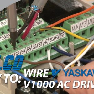
Welcome to G-TV. Today I will be showing you How to wire up
a Yaskawa V1000 AC Drive. It is strongly recommended that the wiring
of your drive should be done with an experienced technician to prevent any damage to the unit
or operator. The drive and wires should not be live during
the installation process and should be removed from any power source. I will start by showing where the three phase
power will be plugged in by removing the front cover that is secured by a screw and then
take off the protective cover on the bottom. The three phase inputs are indicated by the
R, S and T or L1, L2 and L3. I will use these wires to simulate a three
phase power source. The motor can be connected to the right side
of the drive at the connections labeled U, V and W or T1, T2, and T3. To run my drive in remote operation from an
external terminal, I will take a closer look at the I/O terminals. Starting from the top, my terminals R+, R-,
S+ and S- as well as IG are for connecting to my communications network. For this demonstration, I will not be using
a communications protocol.
Next to the IG terminal is a dip switch for
sinking and sourcing which I will talk about later. The next row of terminals has P1, P2 and PC
as my photocoupler digital outputs. The next four terminals of A1, A2, +V and
AC are my analog inputs and main speed frequency reference. I can install a speed pot using the wiper
on either A1 or A2, the second wire on +V and the third wire on AC for the common. The next two terminals labeled AM and AC are
my analog outputs. These terminals can be connected to an external
monitoring device. Next to this is a terminal labeled MP. This is for setting up a pulse train output. Below this is RP on the third row of terminals
and is the pulse train input. The pulse train input is also wired to the
common of my main speed frequency reference input.
To the left of RP is H1. This is a safety switch and must be connected
to HC. If no safety circuit is installed, I can place
a jumper to close the circuit. The SC labeled terminal is tied to the sink
and source mentioned earlier. As a source the SC terminal will supply power
to the connections made and as a sink it will work in the opposite with the power flowing
into the terminal as a common. I will keep the dip switch in the sink mode
and connect this terminal to one of the switches contact blocks. You will notice that my contact blocks are
jumped together.

The other ends of the switches are to be wired
to S1 through S7. S1 is for creating a forward run/stop, S2
is for creating a reverse run stop. This will make forward and reversing two separate
switches and must be maintained switches. S3 is for creating an external fault and can
be a momentary pushbutton. This can be used in place of an E-stop if
I am looking to coast the motor to a stop. It would be the equivalent to removing power
from the drive. S4 serves as a fault reset. This will clear the drive of any fault once
the condition is cleared. S5 and S6 are for multi-speed functionality. They are preset speeds that can be changed
in parameter H1-05 and H1-06. The S7 terminal is the jog reference, which
can be set in parameter H1-07.
My last three terminals on the right are for
setting up a digital output with MA as normally open, MB as normally closed and MC as the
common. Yaskawa V1000 Drives along with thousands
of other products and services are available at galco.com.

